
Data Center
water systemsTrevi builds forward-osmosis systems that turn seawater, brackish groundwater, reclaimed streams, or the data center's own reject water into cooling make-up, driven by low-grade heat.
The Water Constraint on Data Center Siting
Cooling towers lose water to evaporation, and what stays behind concentrates dissolved solids. Operators manage blowdown, chemistry, and a constant make-up demand. Where freshwater is tight, that balance can decide permitting, operating cost, and community acceptance.
Climate, cooling architecture, source-water chemistry, discharge limits, and the site's heat profile set the design. Trevi starts there.
- Candidate sources
- Seawater · Brackish groundwater · Reclaimed water · Produced water
- Thermal input
- Suitable low-grade waste heat · Solar thermal · Other site heat · Data-center cooling-loop waste heat
- Delivered stream
- Cooling make-up water engineered to the site's specification
- Concentrate path
- Reuse · Further concentration · Managed discharge
Recovery, water quality, energy use, and economics come from source chemistry and a site heat balance.
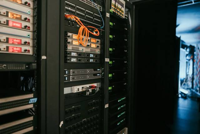
Matching Water Source to On-Site Heat
Trevi's forward-osmosis loop pulls water across the membrane with an osmotic draw solution, then uses heat to separate product water and recycle the draw. The design question: can the site's heat, feedwater, cooling demand, and discharge strategy run as one dependable water system?
- 01
Open the source map
Evaluate non-potable supplies before assuming a new freshwater allocation.
- 02
Design to the cooling system
Set product-water chemistry to the site's tower, liquid-cooling, and treatment requirements.
- 03
Account for the residual
Decide how concentrate and cooling-tower blowdown will be reused, reduced, or managed.
How the Water System Is Designed
A viable project aligns water chemistry, thermal integration, product specification, and residual management.
- 01
Characterize
We characterize hardness, alkalinity, silica, and microbiological indicators alongside the core panel. Cooling loops concentrate chemistry with every cycle, driving scale and biofilm risk.
- 02
Integrate heat
Map heat grade, duty cycle, redundancy, and exchanger approach before assigning recoverable heat to draw regeneration.
- 03
Produce make-up water
Use the FO loop to separate water from the source stream, then polish it to the cooling system's required specification.
- 04
Return water and route concentrate
Return product water to cooling make-up and define the concentrate or blowdown path against site discharge limits.
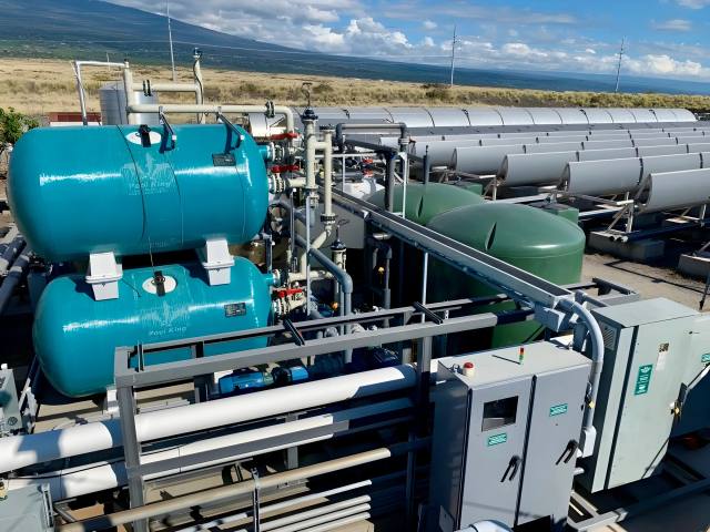
Field Evidence: NELHA, Hawaii
A public third-party report documents a 500 m³/day forward-osmosis seawater plant at the Natural Energy Laboratory of Hawaii Authority, built with U.S. Department of Energy support. Low-grade heat drove seawater desalination at pilot scale.
- 500 m³/day
- Documented plant capacity
- Seawater feed
- Open-ocean source at Keahole Point
- DOE / NELHA
- Agency supporting the pilot program
NELHA is a seawater plant, not a data-center deployment; data-center performance requires a site-specific pilot and design basis.
Request a Site AssessmentBring the water balance and heat profile. We'll show what the site can recover.