
Waste Heat
recoveryTrevi routes industrial waste heat through an engineered thermal interface to regenerate its forward-osmosis draw solution. The output is recovered water, not electricity.
How Waste Heat Drives Water Treatment
Forward osmosis moves water into a concentrated draw solution, leaving it diluted. Trevi's thermal recovery stage applies heat to separate product water and restore the draw for another pass.
Recovered site heat can carry part or all of that duty when its temperature, quantity, and availability fit. Pumps, controls, pretreatment, and polishing still run on electricity.
- Heat source
- Supply and return temperatures, flow, pressure, composition, location, and competing uses
- Engineered interface
- Exchanger and hot-water loop isolate the host process; account for approach temperature, fouling, and access
- Thermal sink
- Useful heat delivered to draw regeneration across startup, turndown, and planned outages
- Water duty
- Heat matched to feed chemistry, product specification, recovery target, and the concentrate route
The design basis is heat delivered at the regeneration interface, not the source's nameplate temperature.
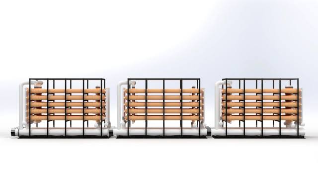
Matching Heat Source to Water Duty
A useful source delivers the right heat at the right time without compromising the host process. A useful sink pairs it with a real water duty. Trevi screens both as one system, with ThermoSnare™ countercurrent polymer heat exchangers at the interface.
- 01
Heat grade at the tie-in
Record supply and return temperatures at the tie-in across normal and limiting cases; exchanger approach and distribution losses set what reaches regeneration.
- 02
Duty across the operating cycle
Provide duty, turndown, seasonal changes, and planned outages. Intermittent heat may need storage or backup.
- 03
Access without disrupting the host process
Define source chemistry, allowable pressure drop, isolation, maintenance access, and the consequence of taking the heat loop offline.
- 04
A matching water demand
Supply the feed assay and flow, required product quality, recovery objective, and residual route.
How a Heat Integration Review Works
The first deliverable is a defensible source-and-sink basis.
- 01
Map the source
Establish supply and return temperatures, duty, flow, pressure, composition, and competing uses across real operating cases.
- 02
Define the water duty
Characterize the feed; set product-water quality, recovery, throughput, and concentrate-management requirements.
- 03
Engineer the interface
Select the exchanger and isolation loop, then check approach temperatures, pumping, materials, cleaning, and host-process safeguards.
- 04
Validate the operating cases
Model startup, turndown, outages, and seasonal limits. Pilot where material uncertainty remains.
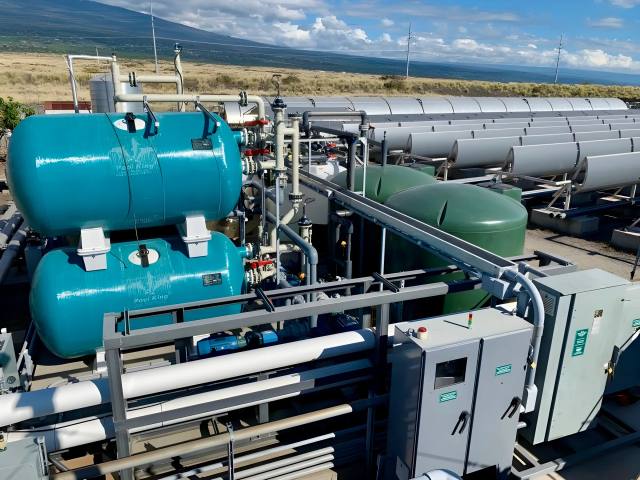
Field Evidence: NELHA, Hawaii
Trevi's project work includes a 500 m³/day forward-osmosis seawater plant at the Natural Energy Laboratory of Hawaii Authority, developed with U.S. Department of Energy support, coupling FO and draw recovery to low-temperature concentrated solar thermal heat.
That proves thermal-source integration with the platform; the economics of a specific industrial waste-heat source depend on the host process and water design basis.
- Evidence level
- Thermal FO pilot reference
- Project capacity
- 500 m³/day stated project capacity
- Feed
- Seawater at Keahole Point
- Thermal source
- Concentrated solar thermal; not industrial waste heat
Delivered water, duty, and economics require a site-specific heat and water balance.
Request a Heat Integration ReviewBring the source and return temperatures. We'll tell you what water that heat can produce.